Graphs are versatile data structures that can represent and solve for many different and unique real-world scenarios. For example - graphs can represent electronic circuit boards, roads and intersections within a city, airline routes or roadways connecting different cities, product catalogs, movies and actors etc. Due to their applicability in modeling vast number of real-world scenarios, interview questions on graphs are frequently asked in programming interviews.
Graphs are not core software programming data structures, but they use other core data structures such as arrays, sets etc. to model the graph representations.
Below questions start with the fundamentals of graphs, followed by questions on how to model and code basic graphs.
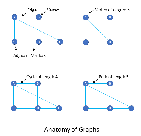
What are the components that a graph consists of?
A graph consists of vertices and edges.
Vertices: Vertices are similar to nodes. Vertices usually have a label for identification in addition to other properties. Examples of vertices are cities in a map and pins in a circuit.
Edges: An edge connects two vertices. Examples of edges are roadways that connect cities in a map, and traces that connect pins in a circuit diagram.
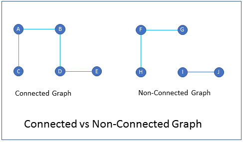
What is the difference between connected graph and non-connected graph?
In a connected graph there is at-least one path from every vertex to every other vertex.
In a non-connected graph every vertex may not be connected to every other vertex.
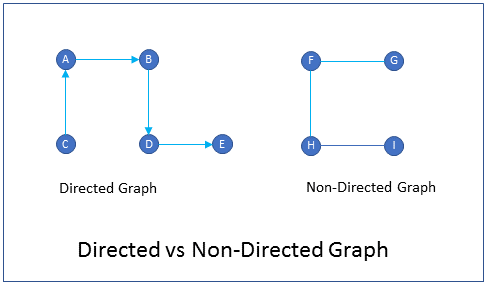
What is the difference between directed graph and non-directed graph?
Directed graphs are graphs in which the edges have a direction. i.e. you can go from vertex A to vertex B, but you cannot go from vertex B to vertex A. An example of a directed graph is a one-way street city map. You can go only one direction on the edge (street) but not the other direction.
Non-directed graphs are graphs in which the edges do not have a direction. i.e. you can go from vertex A to vertex B and vice versa. An example of a non-directed graph is a freeway map connecting cities. You can go both directions on the edge (freeway).
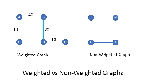
What are weighted graphs?
Weighted graphs are graphs in which edges are given weights to represent the value of a variable. For example in a graph of cities and freeways, the weight of an edge could represent the time it takes to drive from one city to the other. Similarly, in an airline routes graph, the weight of an edge could represent the cost of travel from one city to another.
How do you represent components of a graph in a computer program?
Components of a graph are represented as follows in a computer program.
Vertices - Vertices represent real world objects. For example, in a graph of cities and roadways the vertices represent the cities. Similarly in a graph of a circuit diagram the vertices represent the pins of the circuit board. In a computer program the vertices are modeled as classes having a variable to indicate the label of the vertex, in addition to other variables.
Edges - An edge connects two vertices. In a computer program an edge can be represented in two ways.
1. Adjacency matrix - An adjacency matrix is a NxN matrix whose elements indicate if an edge exists between two vertices. N is the number of vertices contained in the graph. Usually the value 1 is used to indicate that an edge exists between two vertices and the value 0 is used to indicate that an edge does not exist between two vertices.
2. Adjacency List - An adjacency list is an array of lists or sets that contains the adjacent vertices for each vertex of the graph. The parent list contains N elements, one element for each vertex in the graph. Each element contains a list of vertices that that are adjacent to the vertex in the element.
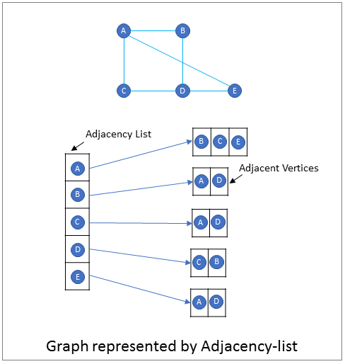
Write a program that represents a graph.
Following is a Java program that represents a graph.
- The vertex is represented by the Vertex class and uses a char for the label.
- An array of length N maintains the list of vertices in the graph.
- An NxN adjacency matrix represents the edges, with 1 indicating that an edge exists and 0 indicating that an edge does not exist.
- The constructor takes the number of vertices as parameter and initializes the arrays.
- addVertex() and addEdge() are methods provided to add a new vertex and a new edge respectively.
//Vertex class
class Vertex{
 private char vertexLabel;
 public Vertex(char vertexLabel) {
  this.vertexLabel = vertexLabel;
 }
}

//Graph class
class Graph {
 //list of vertices
 private Vertex vertexList[];
 //adjacency matrix
 private int adjMatrix[][];
 //number of vertices
 private int nVertices;

 public Graph(int nVertices) {
  //initialize vertex list
  vertexList = new Vertex[nVertices];
  //initialize adjacency matrix
  adjMatrix = new int[nVertices][nVertices];
  for (int i=0; i<nVertices; i++) {
    for(int j=0; j<nVertices; j++) {
      adjMatrix[i][j] = 0;
    }
  }
 }

 //add a new vertex
 public void addVertex(char vertexLabel) {
  vertexList[nVertices++] = new Vertex(vertexLabel);
 }

 //add a new edge
 public void addEdge(int startVertex, int endVertex) {
  adjMartrix[startVertex][endVertex] = 1;
  adjMartrix[endVertex][startVertex] = 1;
 }

}

